On an installed mvBase system, if the number of processes that the Server provides is altered (increased or decreased), then a fileload is required.
Altering the number of processes (in either of the two places described below) causes an immediate fileload from the Boot Tape specified in the Server tab of the Administration Utility. Therefore, if you wish to change the number of processes, perform a full filesave first, ensure that it is specified as the Boot Tape in the Administration Utility, and then alter the number of processes.
Altering the number of processes can be performed in two places:
The Processes edit box, accessed via this path:
Administration Utility > Server tab > Configure button, Processes + Lines tab
The number of processes can only be changed when the mvBase Server is not running. If the Server is running, then the Update… button is unavailable, and prevents changes to the number of processes and lines.
The Options dialog box, which is displayed when the mvBase Server is started as an application and the Autoboot option is off (unchecked).
mvBase allocates a certain amount of frames work workspaces for each process and then the database itself starts at a frame after those workspaces. If the number of processes changes, the number of frames required to be reserved for the workspaces changes. Therefore, the starting position of the database (that is, the BASE of the SYSTEM dictionary) also changes.
Since the entire database now begins from a different position, then a fileload is required to reload the mvBase system and all user accounts.
NOTE |
The existing database is no longer valid and cannot be accessed. |
If removing a Windows tape device driver from the system where mvBase resides, it is necessary to reconfigure all tape devices for mvBase. This is done via the Administration Utility. It is also necessary to reboot Windows.
Perform the following procedure once the tape device driver has been removed from Windows and Windows has been restarted:
Select the Configure… button from the Server tab of the Administration Utility.
Select the Tapes tab.
Remove all mvBase tape devices that represent real tape drives.
Add the tape devices you want to keep.
If a virtual tape file is created on a removable media, and that media is removed prior to the tape being detached, then the length of the virtual tape file is 0.
Discussion
A virtual tape file may be defined from TCL by the use of the SET-TAPEFILE <pathname\filename.vtf> command. If the virtual tape file is on a removable disk media (for example, USB thumb drives), then the media must not be removed before the tape has been detached.
The underlying physical Windows file-system file is still open while the virtual tape is attached. In similar fashion to a traditional physical reel of tape, additional reads/writes may occur while the tape is still attached. The file is closed when the tape is detached. When the file is closed, the length (size) is updated.
Solution
Therefore, to remove the removable disk media, it is mandatory to detach the tape (for example, T-DET) before removing it.
After using BUILD-LOCK-XREF from the SYSPROG account to exclude SYSPROG from update logging, the user must log off and then back on for it to take effect.
A MAXUSERS message may print in error in the following circumstances:
Occasionally when the workstation shuts down.
When a workstation is started prior to completion of the server's coldstart process.
The only consequence of this message is a single-page printing of a MAXUSERS message. In these cases, the maximum number of users has not necessarily been reached. The printed notifications may be disregarded unless secondary notifications are printed subsequent to server startup or workstation shutdown.
To avoid premature printing of MAXUSERS messages, ensure that the Server completes the coldstart process and printers have executed the STARTPTR command prior to starting the workstation.
When you use multiple client types, you may experience an unintentional conflict in line availability. Here are two hypothetical examples:
If a user starts too many mvTerm sessions, they may consume lines specifically allocated to Telnet Clients in the mvTelnet Server.
If you temporarily disconnect a printer and a user starts too many Telnet sessions, you may find that the line is no longer available when you attempt to reconnect that printer.
The table below summarizes the three ways in which mvBase Clients consume lines. When you understand these concepts, you may be able to plan out a better line consumption strategy that prevents unintentional line consumption.
mvBase Clients consume mvBase lines in the following three ways:
A client of type... |
consumes lines by... |
Wildcard |
searching at the lowest mvBase line number (within the entire set of mvBase lines) and consuming the first available line. |
Line-Pooling |
searching at the lowest mvBase line number within a previously defined set of lines, and consuming the first available line within that set of lines. |
Line-specific |
consuming the one specific line allocated to it. |
The table below summarizes line-consumption methods for each standard mvBase Client.
mvBase Client |
Where Lines are Configured in |
mvTerm |
the mvTerm Client. |
COM port clients (serial printers, terminal devices) |
the Ports tab of workstation. |
Windows Printers |
the Printers tab of workstation. |
Telnet Clients connected via the mvTelnet Server |
the Telnet Servers tab of workstation. |
mvBase Client |
Where Lines are Configured in |
Line Consumption Limits |
Line Consumption Methods |
mvTerm |
the mvTerm Client |
One line per session |
One line per Telnet session |
COM port clients (serial printers, terminal devices) |
the Ports tab of workstation |
One line per connected COM port |
Wildcard or line-specific |
Windows Printers |
the Printers tab of workstation |
One line per connected printer |
Wildcard or line-specific |
Telnet Clients connected via the mvTelnet Server |
the Telnet Servers tab of workstation |
One line per Telnet session |
Wildcard, line-specific, or line-pooling |
NOTE |
mvBase includes the mvTelnet Server as a standard feature. Powerful and cost-effective Telnet Clients are available through third-party vendors. mvTelnet governs lines allocated to Telnet Clients. |
In circumstances where you require highly-controlled line consumption, follow one of these three approaches:
Method 1
To ensure general line availability with less concern about security:
Configure the Server with a high number of processes.
Start with a lesser number of lines, and gradually increase the number of lines as client demand requires.
Once you have defined the number of processes, a fileload is not required merely to increase (or decrease) the number of lines.
Method 2
To implement a more stringent level of security:
Use no wildcard clients.
Allocate specific line numbers exclusively to non-wildcard clients.
Limit tightly the quantity of extra lines or phantom lines.
Closely monitor line-consumption (for example, issue LISTLINES at TCL).
Method 3
To implement the highest level of security in line consumption:
Keep each client (of any type) continually connected via its intended line.
Limit tightly the quantity of extra lines or phantom lines.
Closely monitor line-consumption (for example, issue LISTLINES at TCL).
In most cases, such rigid control may not be required. However, but when combining wildcard clients with non-wildcard clients, you may wish to safeguard line availability for both.
mvTelnet Considerations
When configuring multiple mvTelnet Servers, each using a single dedicated line and TCP port, Rocket recommends using a consecutive sequence of lines and TCP ports. Customary TCP ports are ports 23, and 1024-5000. To reduce the likelihood of encountering a previously consumed port when configuring the sequence, Rocket recommends starting with port 2000. Line configuration should follow the recommendations made earlier. mvTelnet Servers are configured with the Telnet Servers tab of the mvBase Workstation.
Note, however, that this approach cannot guarantee resolved conflict with other line or TCP port consumption.
Configuring Line Consumption for Multiple Client Types
This procedure configures coordinated line consumption when multiple client types are used. This requires familiarity with multiple configuration instructions in the mvBase Installation Guide.
Configure known printer(s) to take the highest line number(s). Printer line requirements and usage are unlikely to change frequently, but it is important to safeguard line availability for printers, even when they are not connected.
Configure all line-specific and/or line-pooling clients to take the next lower series of line numbers.
Leave the lowest line numbers open for any required wildcard clients.
Troubleshooting Line Consumption
If you have implemented coordinated configuration of line consumption and one or more clients of any type cannot connect via their intended line(s), the likely cause could be one of these:
More wildcard clients than anticipated may be connected. For example, a user of a wildcard mvTerm or Telnet Client may open more instances or sessions than the administrator planned, prematurely consuming low line numbers.
Clients intended to connect as non-wildcard clients may be connected as wildcard clients, prematurely consuming low line numbers.
The Disconnect on Logoff option in the Ports tab may not be selected when it needs to be. This possibility pertains to configuration of clients connecting via a COM port. Access the Ports tab via the Configure button on the Workstation tab.
Additional lines and/or licenses may be required. Additional lines may be added without performing a required fileload. Contact your local Rocket representative for licensing options.
Should the need arise to completely reinstall Windows, then it is extremely important to be aware of the following:
The mvBase activation code is tied directly to the system ID. This association is critical in maintaining licensing.
If you reload and/or reinstall Windows, the system ID will change. This causes the existing activation code to be invalid.
The mvBase Server will not start as an application or service if the activation code is invalid (or if the system ID does not belong to the system on which it was generated).
Should files become corrupted as a result of any system anomalies, an ABS/Kernel restore procedure must be performed. Restoration can be performed from mvBase source files located on either CD-ROM or floppy diskette media.
CD-Based Restore
Locate the files mvserver.abs and mvserver.knl (these files are in expanded format). These are found in the \support\server directory on the mvBase CD-ROM.
Copy these files from the CD-ROM to the installation directory located on the mvBase Server (<install directory>\server).
Change the attribute for each file from READ-ONLY to ARCHIVE. The attribute setting is located on each file's Properties dialog box. To access this dialog box, right click on the file in File Manager or Windows Explorer and select Properties. The Properties dialog box can also be accessed via the File menu.
Floppy Diskette-Based Restore
NOTE |
Floppy diskettes have insufficient space for file expansion. Expand the files directly to the destination directory on the mvBase Server. |
Locate the mvserver.ab_ file in the root directory of the mvBase diskettes. This file is not in expanded format.
Open MS-DOS or a Windows command shell to expand the file. To expand files in the mvBase Server subdirectory, enter:
EXPAND A:\sourcefile C:\destination |
where:
A:\ |
Drive to the file that is to be expanded. |
Sourcefile |
Path to the file that is to be expanded. |
C:\ |
Drive for file in its expanded format. |
destination |
Path of the file in its expanded format. (<mvBase install directory>\server). |
Once the ABS/Kernel restore has been completed from the mvBase source files, you are back to the base ABS level. If a patch has been previously loaded it must be reinstalled before users can be allowed on the system again.
The procedure to restore accounts from other MultiValue environments is determined by whether or not the accounts require resizing.
Restoring Accounts Without Resizing
If the files do not require resizing, use the ADD-ACCOUNTS PROC to restore accounts from a previous MultiValue installation.
Select the appropriate media (floppy, tape), using T-SELECT.
Type:
ADD-ACCOUNTS |
The media type selected and the block size displays, followed by a list of the files being restored that are not already installed.
Restoring Accounts With Resizing
If the SAVE verb was used with the C option (or the Compatibility option on that particular system) to save accounts from a previous MultiValue installation, resize the files and SYSTEM files using the RESTORE SYSTEM * verb.
Select the appropriate media using the T-SELECT command.
Type:
T-ONLINE RESTORE SYSTEM * (R |
The RESTORE verb is used by the ADD-ACCOUNTS PROC to restore accounts from FILE-SAVE media to the system. The R option enables file resizing in your accounts. This is necessary when moving accounts between systems using different frame sizes. (The larger the frames, the fewer frames needed to hold the same data.)
The message below displays:
Tape producer data frame size = |
Enter the frame size (in multiples of 500 bytes) of the operating system from which you are upgrading.
When starting RESTORE, you may receive the message:
Account 'RESTORE-ERRORS' exist. Delete and (C)ontinue or (Q)uit? |
This message displays if a restore operation (:FILELOAD or ACCOUNT-RESTORE) was previously run. It indicates that the status of that operation (either error messages or a success message) is stored in the RESTORE-ERRORS item.
Type C to continue.
Type this command in SYSPROG to display the RESTORE-ERRORS item:
LIST-ITEM RESTORE-ERRORS |
Use the LPTR option to print the report.
When converting tapes from other products to mvBase, follow the procedure appropriate to your environment.
Account saves from Advanced PICK are supported in mvBase. To convert tapes from Advanced PICK to mvBase, delete and recatalog pointers following these steps:
NOTE |
Perform this procedure for each BASIC program file on the account. Steps 1-11 are performed on the Advanced PICK system. |
Delete the object code from the dictionary files. The object code may occupy too much disk space on mvBase, depleting overflow. (Source code must be recompiled on mvBase.)
NOTE |
Since mvBase does not recognize existing entries as catalog pointers, perform the following steps to delete catalog entries. |
Type:
SELECT DICT sourcefile |
This specifies items in the source file dictionary for further processing.
Type:
SAVE-LIST OBJECT.CODE |
This saves the selected list of all object code in the sourcefile dictionary.
Type:
GET-LIST OBJECT.CODE |
This retrieves the previously saved select-list.
Type:
SELECT MD WITH *A1= "VR" AND WITH *A2="3]" |
This selects all cataloged pointers.
Type:
SAVE-LIST CATALOG.POINTERS |
This saves all programs cataloged from sourcefile.
Type:
GET-LIST CATALOG.POINTERS |
This retrieves the previously saved select-list.
Type:
DECATALOG DICT sourcefile |
This removes the catalog.
Perform the ACCOUNT-SAVE. Use the C option to maintain compatibility.
NOTE |
Items over 32 KB are not saved when the C option is used. |
Use one of these two following methods to save larger items.
Save these items separately using T-DUMP. This method is a more trouble-free way to transfer data but may be tedious if accounts have more than a handful of files.
Split the items over 32 KB in size. Write a program which creates items with a suffix, such as PROG1.001, PROG1.002, and so on.
NOTE |
Consider writing a program to review all files in the account and display those files with item size over 32 KB. |
From the SYSPROG account, perform the ACCOUNT-RESTORE on the mvBase Server system.
Run the UPGRADE program from the SYSPROG account.
Handle items over 32 KB in size by T-LOADing (or combining) items.
NOTE |
When the ACCOUNT-RESTORE is started, mvBase may indicate that the tape label is incorrect. Select the option to move the tape forward, then continue as usual, entering the account name on the tape. |
Compile all of the programs in sourcefile.
Type:
GET-LIST CATALOG.POINTERS |
This retrieves the previously saved select-list. This and the final step catalog the entries.
Type:
CATALOG sourcefile |
This catalogs only what was already cataloged on the old system.
When converting tapes from other products to mvBase, follow the procedure appropriate to your environment.
NOTE |
When executing FILE-SAVE during migration from Mentor-family products to mvBase, or vice versa, only certain devices are compatible. Please refer to the following table for compatibility. |
Migration From: |
Migration To: |
8mm |
4mm |
1/4-inch |
Floppy |
Mentor PRO |
mvBase |
No |
No |
Yes |
Yes |
|
(multi-reel) |
No |
No |
No |
No |
mvBase |
Mentor PRO |
Yes |
Yes |
No |
No |
|
(multi-reel) |
No |
No |
No |
No |
Perform the following step:
Run the UPGRADE program from the SYSPROG account.
When converting tapes from other products to mvBase, follow the procedure appropriate to your environment.
NOTE |
When executing FILE-SAVE during migration from Mentor-family products to mvBase, or vice versa, only certain devices are compatible. Please refer to the following table for compatibility. |
Migration From: |
Migration To: |
8mm |
4mm |
1/4-inch |
Floppy |
Mentor PRO |
mvBase |
No |
No |
Yes |
Yes |
(multi-reel) |
No |
No |
No |
No |
|
mvBase |
Mentor PRO |
Yes |
Yes |
No |
No |
(multi-reel) |
No |
No |
No |
No |
Perform the following steps:
Run the UPGRADE program from the SYSPROG account.
Recompile all BASIC programs.
When transferring data from other products to mvBase using tapes, follow the procedure appropriate to your environment. This procedure assumes that you are using quarter-inch tape as the medium of choice.
NOTE |
R91 and Power95plus allow larger tape block sizes than mvBase can read. |
On the R91 or Power95plus system:
Put in a new quarter-inch tape cartridge and perform SET-CT <unit#> (default is 0).
NOTE |
Be sure the drive is clean and the tape media is compatible with the tape drives on both the R91 and mvBase systems. |
Type:
T-ATT 16384 |
This is the size that will be used to read the tape on the mvBase system later. This sets the block size for quarter-inch tapes (R91 normally defaults block size to 24576 for quarter-inch tapes).
Save the desired accounts by using the SAVE verb with the backward compatible (C option. For example:
For one account:
SAVE SYSTEM <account_name> (CTIG |
For ALL accounts:
SAVE SYSTEM * (CTIG |
To verify that the taped saved correctly, rewind the tape and perform RESTORE SYSTEM * (V. The (V option reads the tape data and checks the format for correct consistency.
General Notes
BASIC Object code is not saved to tape.
Binary linked items are not saved to tape.
Binary items that are not in a DC file are not saved to tape.
Items over 32 KB are not saved to tape. Explicit T-DUMPs and T-LOADs of these items in each file should be used to transfer these between the systems.
The SAVE-LOGS should always be viewed after the SAVE in order to identify any problems as well as data that was not saved. This can be found in the System Manager's SAVE-RESTORE menu.
Because each system and version varies slightly, the system manuals should be reviewed for any differences that may exist. This information is presented as a generic procedure for most systems.
On the mvBase system:
Floppies have a max block size of 500.
quarter-inch cartridges have a max block size of 32256, but defaults to 16896.
This procedure will use a block size of 16384 (16 KB) though, explicitly.
4mm DAT Tapes default to 16384.
The mvBase system (and some media formats) has a maximum block size of 32256.
Assuming quarter-inch tape:
Type:
T-SELECT x |
where x is the Logical Tape Unit # of the device you wish you use).
Type:
T-ATT 16384 |
Perform the ACCOUNT-RESTORE, or ADD-ACCOUNTS command, (or use the RESTORE verb directly if you are familiar with its options).
Run the UPGRADE program on each restored account from the SYSPROG account.
Recompile and recatalog all BASIC programs.
When converting tapes from other products to mvBase, follow the procedure appropriate to your environment.
ACCOUNT-SAVES from Sequoia Pick are supported in mvBase. Perform these steps to convert tapes from Sequoia Pick to mvBase.
Perform the ACCOUNT-SAVE with the B option. For example:
SAVE (DFSTIB |
Enter the account name when prompted.
Perform the ACCOUNT-RESTORE on mvBase using the B, Y, and R options. For example:
ACCOUNT-RESTORE account-name (B,Y,R) |
The B option ignores size errors. Note that binary items requiring more than 255 frames are not restored.
The Y option is used to prevent the conversion of CL items, restoring them as linked binary items.
The R option allows users to specify frame size on the system that created the account.
Run the UPGRADE program from the SYSPROG account. Type:
SET-FILE account-name MD COPY NEWAC * (O) To:(QFILE COPY MD ERRMSG (O) To:(QFILE |
If the account logon Proc (QFILE account-name) runs any BASIC programs, type:
ED QFILE account-name .G1 .I 001+ X <cr> .FI LOGTO account-name |
Recompile all BASIC programs.
If you inserted an X in the account's logon Proc, you can remove it.
To ensure that Procs using STON work as they did on SEQUOIA Pick, type:
SYSTEM-SWITCH |
Enter the name of a class or switch (or to stop):
SET-PROC-STON |
The current setting displays.
If it is not ON, take the T option to toggle the setting to ON.
Digiboard drivers prior to Version 2.3.0 (known as Release S) for Windows appear to contribute to an output stalling problem. This stalling problem manifests itself on terminals connected to Digi Terminal Concentrators. No more output appears on the terminal, including that of entered characters being echoed. This condition usually shows up by the mvBase process for the affected line having a persistent PIB status of 7F20 (as displayed by the WHERE TCL command).
This could occur in either of the following conditions:
The Digi Host Adapter is physically located in the system running the mvBase Server (thus controlled by the local mvBase Workstation).
The Digi Host Adapter is in a different system to the mvBase Server (and thus controlled by the remote mvBase Workstation on that remote system), although this situation has not yet been directly observed in the field.
Digi driver releases that have been shown to manifest this problem include v2.1.0 (known as the R release) and v2.2.6 (the 4PS S beta release). The S release, v.2.3.0, has been tested with mvBase and not shown to exhibit this problem.
Rocket recommends implementing these actions to prevent stalled output:
Obtain and install new Digiboard drivers from the Digi International Web Site:
http://www.digi.com/support/index.jsp
Always obtain the latest drivers available for your Digi product, specific to your operating system and platform.
When converting tapes from other products to mvBase, follow the procedure appropriate to your environment.
Account saves from D3 are supported in mvBase. To convert tapes from D3 to mvBase, delete and recatalog pointers following these steps.
NOTE |
Perform this procedure for each BASIC program file on the account. Steps 1-10 are performed on the D3 system. |
Delete the object code from the dictionary files. The object code may occupy too much disk space on mvBase, depleting overflow. (Source code must be recompiled on mvBase.)
Since mvBase does not recognize existing entries as catalog pointers, perform the following steps to delete catalog entries.
Type:
SELECT DICT sourcefile |
This specifies items in the source file dictionary for further processing.
Type:
SAVE-LIST OBJECT.CODE |
This saves the selected list of all object code in the sourcefile dictionary.
Type:
GET-LIST OBJECT.CODE |
This retrieves the previously saved select-list.
Type:
SELECT MD WITH *A1= "VR" AND WITH *A2="3]" |
This selects all cataloged pointers.
Type:
SAVE-LIST CATALOG.POINTERS |
This saves all programs cataloged from sourcefile.
Type:
GET-LIST CATALOG.POINTERS |
This retrieves the previously saved select-list.
Type:
DECATALOG DICT sourcefile |
This removes the catalog.
Perform the ACCOUNT-SAVE. Use the C option to maintain compatibility.
NOTE |
Items over 32 KB are not saved when the C option is used. |
Use one of these two following methods to save larger items.
Save these items separately using T-DUMP. This method is a more trouble-free way to transfer data but may be tedious if accounts have more than a handful of files.
Split the items over 32K in size. Write a program that creates items with a suffix, such as PROG1.001, PROG1.002, and so on.
NOTE |
Consider writing a program to review all files in the account and display those files with item size over 32 KB. |
From the SYSPROG account, perform an ACCOUNT-RESTORE (B on the mvBase Server system.
An error similar to Invalid File Definition item accname may occur, where accname is the name of the account that is to be restored. A prompt similar to Enter new modulo = then displays. It is asking for a modulo for the account definition item.
Type:
27 |
Run the UPGRADE program from the SYSPROG account.
Handle items over 32 KB in size by T-LOADing (or combining) items.
NOTE |
When the ACCOUNT-RESTORE is started, mvBase may indicate that the tape label is incorrect. Select the option to move the tape forward, then continue as usual, entering the account name on the tape. |
Compile all of the programs in sourcefile.
Type:
GET-LIST CATALOG.POINTERS |
This retrieves the previously saved select-list. This and the final step catalog the entries.
Type:
CATALOG sourcefile |
This catalogs only what was already cataloged on the old system.
Introduction to mvBase Licensing
mvBase licensing assigns one license per physical user connected to mvBase, and reflects the number of users connected to mvBase. The number of users may or may not necessarily reflect the number of connections. mvBase licensing is not based on the number of connections actually logged on.
This concept allows users on Windows PCs (using the mvBase virtual terminal mvTerm, or a third-party Terminal Emulator such as wIntegrate*) to have multiple connections (and thus multiple log ons) to an mvBase Server without consuming additional licenses.
Telnet Clients and Sharing mvBase Licenses
Telnet Clients are defined as any client that communicates with the mvBase Server via an mvTelnet Server running as part of an mvBase Workstation. These include the Telnet Client that Microsoft supplies with Windows, wIntegrate* and other third-party PC-based terminal emulators, and Telnet clients supplied with, or running on, OS/2, UNIX, MAC and other operating systems.
Sharing a license occurs when an individual user opens a first connection. This consumes one license. Subsequent connections "share" the first license. However, even if the original connection is disconnected, as long as any of the connections that shared this license are open, the user will continue to consume one license. In other words, for any one user there will be a minimum and a maximum of one license consumed when license sharing occurs.
User Choices for mvBase License Consumption
Users of Telnet Clients running on a Windows PC may choose how their license consumption occurs, and may connect to an mvTelnet Server in one of these two ways:
To an mvTelnet Server running as part of a LOCAL mvWorkstation (on the same system as the mvTelnet Client). These may have multiple connections to a mvBase Server which share a single license. Third-party terminal emulators, such as wIntegrate*, are treated in exactly the same manner that the mvBase Virtual Terminal is treated with regard to license consumption.
To an mvTelnet Server running as part of a REMOTE mvWorkstation (on a different system from the mvTelnet Client). These may have multiple connections to a mvBase Server. Each connection consumes one license, with no sharing.
Users of Telnet Clients running on other platforms may not choose how their license consumption occurs, and will automatically consume one license for each Telnet connection.
Using USYSTEM() to Determine License Consumption
Three USYSTEM() function calls in mvBASIC return license-related information:
USYSTEM(201) returns the number of current licenses in use by connections.
USYSTEM(202) returns the number of total connections.
USYSTEM(203) returns the maximum number of licensed connections purchased. This number can also be seen in the Administration Utility, Server tab, Authorization button.
The stop button can be used as long as power fail has been enabled. The way to enable power fail is to log to SYSPROG and issue a DELETE ERRMSG POWERFAIL from TCL and restart mvBase. Once power fail has been enabled, the stop button will now perform an orderly shutdown of the mvBase server component when pressed.
Rocket recommends that no spaces be used in the mvBase Server system name. For example, the hypothetical server name Alpha One should be renamed Alpha_One. This may help to prevent problems with certain mvBase components.
mvBase currently has 1023 frames available for use by system and third-party software. The modes (object code) for the software are loaded into the ABS frames (or absolute address).
Certain frame number ranges are in use by, or reserved for, mvBase itself; others are reserved for use by third-party products. These latter frames are known as User Frames for use by User modes - mvBase does not use these, although other third-party products may.
Rocket does not reserve any of these user frames for a specific product. Third-party developers are free to use any combination of them. To avoid conflict with other third-party products, it may prudent to make third-party products' code relocatable.
Frames reserved for USER modes
430-548 Except 489
There are several other blocks of frames used by Mentor Software products. If these will never be in concurrent use with a particular third-party product, then they are also available:
549-575 Mentor/Link
620-660 CompuSheet
The first choice for frame numbers to use should be the USER reserved areas mentioned above.
Virtual Tapes behave in an identical manner to physical reels of tape on physical tape drives.
When using physical reels of tape, the tape is rewound (using the T-REW command) before being removed from the drive (dismounted) and mounting a different tape.
A Virtual Tape must be rewound (using the T-REW command) before mounting (using SET-TAPEFILE) a different Virtual Tape on the same Logical Tape Unit (LTU).
Failure to do this may cause any data written to the second (newly mounted) virtual tape to start far into the tape at the point where the previous (dismounted) virtual tape was positioned. The tape before that position will appear to contain blanks.
Rewinding the previous virtual tape before dismounting it and mounting a new virtual tape causes the new virtual tape to be positioned at the beginning of the tape.
The example below illustrates the problem.
T-SELECT 5 SET-TAPEFILE C:\SALES\WESTERN.VTF T-ONLINE ACCOUNT-SAVE WESTERN.SALES |
(Note no T-REW at this point!)
SET-TAPEFILE C:\SALES\EASTERN.VTF ACCOUNT-SAVE EASTERN.SALES T-REW T-DET |
At this point WESTERN.VTF is just fine, but EASTERN.VTF has as many nulls at the front as there were characters in WESTERN.VTF.
mvBase supports using two systems to provide a hot standby for a live system. This feature is known as Fast Fault Recovery (FFR) and is a set of procedures rather than specific pieces of software. FFR depends on inter Transaction Logging (TL) to move file updates from the live system to the standby system. This ensures that the two copies of the database are kept in synch.
On any system, even without FFR, Transaction Logging can be performed and the data written to a tape device, thus creating a set of log tapes. These can be used to restore transactions should a catastrophic system problem occur. The restore can take place on the same system, once the problem has been resolved, or on a spare system after the full database has been File loaded from the most recent File Save. FFR allows virtually real-time, automatic (requiring no operator intervention) updates of the standby system to occur.
On mvBase the tape device can be a virtual or physical hardware tape drive. The two types of virtual tape devices are the Virtual Tape Link (VTL) and the Virtual Tape File (VTF). The Virtual Tape Link allows a communications link between the two systems to function as a pair of tape drives. Transactions are logged on to the VTL on the live system while transactions are read from the VTL on the standby system so they can then be applied to the standby database.
Depending upon the number of file updates being generated on the live system, Transaction Logging performed over a Virtual Tape Link could generate a significant amount of network traffic. If the network interface card(s) and physical network are being used for other purposes (normal file and print serving, or more likely, to connect the mvBase Clients to the mvBase Server), then overall user response may suffer.
If this occurs, the solution is to place an additional Network Interface Card (NIC) in the both systems connected directly to each other over a separate crossover network cable (see below).
The steps below serve as a guide to set up this configuration. It does not describe the creation of Virtual Tapes Links, or the use of the Transaction Logger. These are documented in the user manuals.
Install 2 Network Interface Cards in each system and ensure that they do not have hardware resource conflicts (IRQ's base port addresses).
If the systems are normally called LIVE and STANDBY, to correspond to the (for example) 192.100.100.x subnet IP addresses, then the secondary NIC's IP addresses (192.100.101.x) will be resolved from different names (say LIVE_FFR and STANDBY_FFR). Thus, each physical system will have two names which resolve into two different IP addresses, each on a different subnet and connecting through a different NIC.
Configure the first card on each system to be on your normal network subnet by allocating an appropriate IP address and associated netmask, then setup its default gateway. For example:
LIVE Nic 1: IP Address: 192.100.100.1 Netmask: 255.255.255.0 STANDBY Nic 1: IP Address: 192.100.100.2 Netmask: 255.255.255.0 |
Configure the second card on each system into a different subnet. For example:
LIVE_FFR Nic 1: IP Address: 192.100.101.1 Netmask: 255.255.255.0 STANDBY_FFR Nic 1: IP Address: 192.100.101.2 Netmask: 255.255.255.0 |
Install a crossover Ethernet cable between the two secondary cards (that is, the 192.100.101.x cards) or connect the cards to their own dedicated network segment by having a single hub with only these two cards connected to it.
Add an entry into the hosts file which is located in (%systemroot%\system32\drivers\etc\hosts) on both systems as follows:
On LIVE: 192.100.101.2 STANDBY_FFR On STANDBY: 192.100.101.1 LIVE_FFR |
Reboot both servers and test using ping that you are in fact routing the network traffic through the right cards.
On LIVE, do a ping 192.100.101.2 (or a ping STANDBY_FFR) and watch the individual link active lights on the hub to see if the hub port connected to the secondary NIC's on LIVE and STANDBY are being used.
If the two systems are directly connected with a crossover cable, then the Network Monitor utility should be used instead of a hub to examine traffic on the subnet (192.100.101.x).
Finally, verify that you can still access both systems via their primary NICs from elsewhere on the main network.
There are reported instances of Telnet connections to an mvBase mvTelnet Server being slow to establish. This is manifested as the length of time between these two events:
When the user's telnet client establishes a telnet connection with an mvBase mvTelnet Server.
On some telnet clients, when the telnet connection itself is established, the title bar of the telnet client window changes to show the name of the system connected to.
When the mvBase mvTelnet Telnet Server connects to a line on an mvBase Server. When the mvTelnet Server connects to a line on the mvBase Server the following message displays:
Welcome to the mvBase telnet server.
You are connected to line 1 on \\some_system_name
The time delay between these two events has been reported to be as long as 15 seconds to over 45 seconds. However, once the connection to the mvBase Server has been established, then communication and response speed is satisfactory.
Cause
The problem occurs when the mvBase mvTelnet Telnet Server attempts to find the name of the system on which the telnet client is running.
Here, we are trying to get the name of the client given its IP address. The name is one part of what is called host information.
To look up the host information corresponding to a network address the networking support in the Windows operating system will do the following:
If an entry for a DNS server address exists in the system's TCP/IP networking configuration, then Windows will attempt a reverse DNS lookup.
The reverse look-up is done after the Telnet Client connects to the mvTelnet Telnet Server and before mvTelnet connects to a line on an mvBase Server. The delay is the result of the network timeout when a DNS server is defined but unreachable, or non-existent.
If there is no DNS defined, or the DNS lookup fails, then the NetBIOS cache on the local system is consulted. This is originally established from the HOSTS file (if any).
The HOSTS file must be on the system that is running the mvBase Workstation. On Windows, it lives in %SYSTEMROOT%\System32\Drivers\Etc
Regardless of whether the attempt to get the telnet client name from a HOSTS file was successful or not, the delay has already been caused by the failed attempt of the reverse DNS lookup.
Resolution
Ensure that the TCP/IP settings for the network card being accessed has its DNS settings correctly configured.
If the DNS search order is pointing to a DNS server that cannot be reached or does not exist, then you will experience delays until the DNS request times out.
To verify the DNS settings you need to go to Control Panel > Networks > Protocols > TCP/IP (for that adapter) > DNS. If you have a DNS server in the DNS search order listbox, you need to ensure that it exists and is reachable on your currently connected network. If the DNS Server does not exist, remove that entry.
If there are multiple entries in the DNS lookup search order, then check that each one exists and is reachable.
Notes
One common mistake that is made on laptop computers is to connect the laptop to the network and configure the network card to use static IP addresses and specific DNS, WINS settings, and so on.
When the laptop is not connected to the network, then these addresses are still being used, but the DNS/WINS components are no longer reachable. Trying to telnet to an mvBase mvTelnet Telnet Server on the laptop itself then encounters the problem above.
Rocket recommends that you avoid setting up client computers using static IP addresses and settings. Instead, go to a Microsoft DHCP (Dynamic Host Configuration Protocol) environment for the network settings.
This problem with unreachable or non-existent DNSs may also occur on a client computer (instead of the Windows system where the mvBase Workstation is running). In this case, it is the TCP/IP DNS settings on the client that need to be fixed.
In this case, the problem will manifest itself as the length of time between the telnet client being instructed to connect to a system by name (rather than by direct IP address), and the name resolution completing (or failing totally).
The networking support in the Windows operating system always resolves system names to IP addresses as below. This is what the Telnet Client may have had to do (unless it was given an IP address to connect to instead of a name), and is the opposite of what we are doing here on the Telnet Server.
If the name is not a Fully Qualified Domain Name (FQDN), such as mordac.misp.com, and is just a system name like mordac, then the name will be looked up as follows:
If a HOSTS file exists, it will be consulted first.
If there is no HOST file, or it does nor contain the required entry, then the LMHOSTS file will be consulted.
If a WINS (Windows Internet Naming Service) Server is configured on the network, Windows will try to resolve the NetBIOS name to an IP address.
If no WINS is available, or it does not contain the desired entry, then a DNS lookup will be done.
If the name is a Fully Qualified Domain Name (FQDN) like mordac.misp.com, then only a DNS lookup will be done.
4mm tapes produced on A/P may cause problems when read on an mvBase system. Specifically, an error message saying 'PARITY ERROR' may occur when an attempt is made to read the first block.
The format on such tapes is unusual for 4mm tape. It uses 512 byte fixed-length blocks (physical not logical blocking) and 80 byte labels embedded in 512 byte physical blocks.
While this is unusual for 4mm, it is exactly the format mvBase uses for quarter-inch. Knowing this makes the workaround below effective.
Workaround
Since the 4mm tape appears to be written using a quarter-inch format, you need to change the mvBase type of the tape drive to QTR-INCH.
Delete and then add again the 4mm tape drive using the mvAdmin. When prompted for the type of drive, specify QTR-INCH.
Because drive type specification in mvBase is soft and not determined by the hardware/driver, this will be successful.
Restart the mvBase Server.
The 4mm tape drive now displays as a QTR-INCH drive under T-STATUS.
At this point, it should be possible to perform ADD-ACCOUNTS, ACCOUNT-RESTORE, and SEL-RESTORE from an A/P filesave or T-LOAD's from an A/P T-DUMP. It should also be possible to write A/P compatible 4mm tapes as well.
Limitations
Reconfiguring the 4mm tape drive to be viewed by mvBase as a quarter-inch drive has to be done in mvAdmin while the mvBase Server is not running.
While the 4mm drive is configured as a quarter-inch drive, it can no longer correctly read or write standard format (mvBase compatible) 4mm tapes. The tape device becomes a dedicated A/P compatible tape device, at least until reconfigured by mvAdmin.
This issue deals with the physical formatting of the tape blocks by the tape driver. There are still logical format incompatibilities between mvBase and A/P in File-Save that require the use of the (C) option on A/P systems and special procedures for handling large size items.
It is possible to configure mvBase and Windows so that printing may be carried out on a serial printer attached to a Network Terminal Server (NTS). An NTS can be deployed anywhere across the network (LAN,WAN) and provides one or more serial ports (RS232 interface). The following instructions refer specifically to the Digi Port Server II (PSII) and the Systech RSC4000. However the general scheme is applicable to any similar device.
Actual terminals attached to Network Terminal Servers connect to application servers using the Telnet protocol over TCP/IP. Each serial port on the NTS has a separate Telnet session to a Telnet Server on the host system.
Serial printers may be attached to an NTS and handled in the same manner as terminals. Because printers are output devices, they cannot instruct the NTS to establish a Telnet session to the host. Thus, the NTS must initiate the Telnet connection when it is powered up, and re-establish the telnet session automatically if the connection is lost. Not all NTS's are capable of doing this. It is not possible for the host system, where the Telnet Server is, to initiate a Telnet connection to the NTS Because the host system is a Telnet Server, not a Telnet Client.
A viable alternative is to use a feature known as TCP/IP Printing. The NTS runs a piece of software known as lpd (which originally comes from the UNIX world and stands for Line Printer Demon). The Windows system runs the associated facility known as lpr, which is called the TCP/IP Printing Service by Microsoft.
This method requires configuration to set up. The following four sets of steps will guide you through this process. You will need to know the NTS's IP address, the NTS port number(s) to which printer(s) are attached, and how to log on to the NTS itself and get to the NTS command prompt.
Setting up the Microsoft TCP/IP Printing Service
Adding the TCP/IP Printing Service to the Windows configuration:
Right click on the Network Neighborhood desktop icon and select Properties.
Select the Services tab, then click Add.
Select Microsoft TCP/IP Printing, then click OK.
Provide the system with the appropriate Windows CD-ROM when prompted.
Setup will copy some Windows files.
Click Close when this is finished. (Windows will re configure its bindings at this point.)
Remove the CD-ROM.
Restart the entire Windows system when prompted.
Defining Printers on the NTS
Digi Portserver II
To define printers on the NTS:
Log on to the PSII itself from an attached terminal or a telnet session.
Do the following at the PSII prompt (#>):
Set ports range=<port#> dev=prn
Repeat for all printers on the PSII.
Enter boot action=reset
Systech RCS4000
To define printers on the NTS:
Log on to the RCS4000 from an attached terminal or a telnet session.
Log on to the admin user.
Ensure that the port that the printer is attached to does not have any profiles set on it.
Show port x
where x is the port that has the printer attached.
Do one of the following at the prompt (>) if profiles are displayed:
Delete default x to remove the default profile.
Delete Cn x to delete a Custom profile
where Cn is the Custom profile number.
Adding Printers at the Windows Level
To define a new printer to Windows and specify that it uses the TCP/IP Printing Services:
Select Start > Settings > Printers.
Select the Add Printer wizard.
Select My Computer, then click Next.
Click Add Port.
Select LPR Port, then click New Port.
Enter the IP address of the NTS in the Name or address of server providing lpd field.
Enter in the Name of printer or print queue on that server field:
Digi Portserver II: ascii_<port#> |
where port# is the serial port number on the PSII which the printer is attached to. (For example, for a printer on port 8 enter ascii_8)
Systech RCS4000: port<port#> |
where port# is the serial port no. on the RCS4000 which the printer is attached to. (For example, for a printer on port 8 enter port8)
Click OK.
Click Close from the Printer Ports dialog box, then click Next.
Select the Printer Manufacturer and then the Printer from the drop down list boxes, then click Next.
You may wish to alter the name of the printer from the supplied default.
Select the No option to avoid making this printer the default Windows printer, then click Next.
Select the Not Shared option, then click Next.
Select the No option from the Print test page? dialog box, then click Finish.
Repeat for any other printers attached to ports on the NTS.
See Microsoft documentation and/or online help for more details on setting up printers in general and TCP/IP printing specifically.
Adding Printers to mvBase
To define the Windows printer(s) to the mvBase Workstation:
Select Start > Programs > RocketSoftware> mvBase > Administration Utility.
Select the Workstation tab.
Stop the Workstation service (if necessary).
Select the Printers tab.
Click Configure.
Click Add.
Select the printer that was setup above from the Printer Name drop down listbox.
Type the mvBase Server name.
Assign an mvBase line# on that server for exclusive use by the printer.
Select RAW from 'Driver Type' from the drop down. Since many USB printers are "Windows Only printers", if RAW does not work use "Windows-GDI" from the drop down.
Repeat from step 6 for each printer added.
Start the mvBase Workstation.
Log on to mvBase and use the STARTPTR verb to start the mvBase despooler processes, one for each printer/line defined above.
This document is a simple guide to setting up a port on a Digi Portserver II Network Terminal Server to auto-connect to a host using telnet. It also describes how this auto-connection can take effect, without manual intervention from a terminal keyboard. Be aware that if a disconnect is issued to the mvBase line using this port from mvBase, then the connection will terminate. To reconnect, instead of having to stop and restart the mvBase Workstation, manual intervention is required in the form of a terminal power reset, disconnection/reconnection of the cable between the device and the Digi, or any input from a keyboard connected to the terminal on this port.
This is achieved by defining the Digi port type as an Inbound Modem, even when the device being attached is a Terminal (or some other DTE-like device) and not a modem (a DCE device).
We first must set up a user that will be the telnet user name from the point of view of the telnet server on the host system:
Set user name=dts2 |
Each port on the Digi needs to have a user name and user-ID (UID) specified for it. These may be unique or they may be all the same. When connecting to an mvBase Telnet Server the UID is ignored, but the User Name is displayed as the client name.
Now set the port configuration information:
Set port range=2 uid=2 auto=on dest=hostipaddr dport=tcpportno dev=min |
User Name |
Name that appears in listlines as the telnet username |
Range |
Digi port number or range of ports |
UID |
As the digi runs a UNIX O/S, then it needs a UID (although this is ignored) |
Dest |
mvTelnet Server IP address |
Dport |
mvTelnet Server TCP/IP port number |
Dev |
Device type (min = Modem Inbound) |
Set the flow control information to allow the DCD signal from the modem to the Digi to be detected correctly:
Set flow range=2 altpin=on |
altpin=on |
Swaps DCD and DSR signla lines as DCD does not normally appear on the 8 pin RJ45. |
Below is the Recommended Terminal Cabling:
NOTE |
The recommended cable type is CAT 5 grade 8 wire cable, using RJ45 connectors. |
Signal Digi |
Portserver II RJ 45 8 Pin |
Modem DB-25 |
Signal |
Data Carrier Detect |
1 |
4 |
Request to Send |
Request to Send |
2 |
5 |
Clear to Send |
Shield Ground |
3 |
Shell |
Shield Ground |
Transmitted Data |
4 |
3 |
Received Data |
Received Data |
5 |
2 |
Transmitted Data |
Signal Ground |
6 |
7 |
Signal Ground |
Clear to Send |
7 |
20 |
Data Terminal Ready |
Data Terminal Ready |
8 |
8 (also wire to pin 6) |
Data Carrier Detect (and Data Set Ready) |
Data Terminal Equipment (DTE) and Data Communication Equipment (DCE)
Systems COM ports, Digi C/X concentrator ports and terminal ports are considered Data Terminal Equipment devices (DTE) while a modem is considered a Data Communication Equipment device (DCE).
Assuming that the COM ports, C/X concentrators, and terminals ports have DB-25 pin connectors:
To connect to another DTE device a reversing cable is required.
To connect to DCE devices a straight through cable is required.
For terminals, their Data Terminal Ready (DTR) outgoing signal is used for hardware flow control.
For serial printers, the Printer Busy outgoing signal is used for hardware flow control.
For modems the RequestToSend/ClearToSend (RTS/CTS) signals are used for hardware flow control.
A Note on Terminology
The terms input and in, and output and out are used in this document to indicate the direction of data flow with respect to the mvBase system. Data being displayed on terminals, or printed on printers, or sent over modems is considered output. Data being entered from a keyboard or being received from a modem is considered input.
Flow control can be specified for data flows in either, or both directions. Thus, In Flow refers to controlling the flow of data being input to the system, and Out Flow refers to controlling the flow of data being output from the system.
Hardware flow control signals are considered incoming or outgoing with respect to the individual devices. Thus, the DTR signal line attached to the DTR pin on the connector on a terminal is an outgoing signal with respect to the terminal. It is normally connected to the CTS pin on the connector on the DTE device, thus becoming the incoming CTS signal with respect to the DTE device (Systems COM ports, Digi C/X concentrator ports and terminal ports).
Wiring
Wiring Terminals and Serial Printers for Hardware Flow Control
To wire a terminal or serial printer that supports DTR (or printer busy on serial printers) hardware flow control, the terminal's outgoing DTR signal (or serial printer's printer busy signal), usually pin 20, should be connected to the DTE device's (system COM ports, Digi C/X concentrators, and so on) incoming CTS signal pin.
For the 9-pin system COM ports connector, the incoming CTS signal pin is pin 8, for a DB-25 connector this is pin 5. For the Digi C/X concentrators RJ-45, the incoming CTS signal pin is pin 8.
The outgoing RTS signal pin of the DTE device (system COM ports, Digi C/X concentrators, and so on) should be connected to the terminal's incoming CTS signal pin 5.
For system COM ports, the outgoing RTS signal pin is normally pin 7 on a 9-pin connector, and pin 4 on a 25-pin connector.
For the Digi C/X RJ-45 connector, the outgoing RTS signal pin is pin 3.
NOTE |
Port communication configuration changes do not require an mvBase Workstation shutdown. However to avoid a license usage for a serial printer, you must check the serial printer box in the Port Info field, which does require a shutdown and restart of the workstation. |
Wiring Modems for Hardware Flow Control (and connecting two system COM ports back-to-back)
Most modems by default use hardware flow control (RTS/CTS). For 9-pin COM ports, a DB-9 female to DB-25 male modem cable is required. For DB-25 pin COM ports, a straight through cable is required. System's COM ports and Digi C/X concentrators support RTS/CTS hardware.
When connecting between COM ports on two systems, a full reversing cable is required.
Configuring mvBase for Flow Control
Using the mvBase Administration Utility
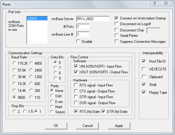
A typical mvBase Ports configuration dialog box displays below.
To access the mvBase Ports dialog box:
Launch or switch to the mvBase Administration Utility.
Select the Workstation tab, and then click Configure...
Select the Ports tab to display the Ports dialog box.
By default, the XIN, XOUT, RTS and DTR state boxes are checked to support software flow control.
Flow Control Options
There are eight Flow Control check boxes that can be set on a port-by-port basis. Although it would appear from the lack of visual grouping that there is no interdependence between them, not all of the possible 256 combinations are either legal or meaningful. Each check box is described below, followed by an explanation of the logical groupings.
There are two directions that flow control can be specified for:
In Flow Control (or Input Flow Control) refers to controlling the flow of data in to the system from a terminal or serial printer.
Out Flow Control (or Output Flow Control) refers to controlling the flow of data from the system to a terminal or serial printer.
Typically, one method of Input Flow Control and one method of Output Flow Control would be specified. The descriptions below are from the point of view of a system that is connected to a terminal, modem, or serial printer device.
Software (in band/XON-XOFF) Flow Control Options
XIN Flow
When checked, the system is the initiator of sending Control-S (ASCII DC3) to halt input from the terminal or modem into the system, or Control-Q (ASCII DC1) to resume it. Thus, XIN flow is describing controlling input to the system, which is coming from the terminal or modem.
XOUT Flow
When checked, the terminal or serial printer is the initiator of sending Control-S to halt output to the terminal or serial printer from the system, or Control-Q to resume it. Thus, XOUT flow is describing controlling output from the system, which is going to the terminal, modem, or serial printer device.
Hardware (signal-based) Flow Control Options
RTS In Flow (similar to XIN flow, but uses the RTS
signal pin instead of the
XON/XOFF software flow control mechanism).
When checked, the system's outgoing RTS signal controls the flow of data being input to the system from a terminal or modem. When the signal is high, it indicates that the system is ready to receive data, when the signal is low it indicates that the system is not ready to receive data.
CTS Out Flow (similar to XOUT flow, but uses the CTS signal pin instead of the XON/XOFF software flow control mechanism).
When checked, the incoming CTS signal from the terminal, modem, or serial printer device controls the flow of data being output by the system to the terminal, modem, or serial printer device. When the signal is high, it indicates that the terminal, modem, or serial printer is ready to receive data. When the signal is low, it indicates that the terminal, modem, or serial printer is not ready to receive data.
DTR In Flow (similar to RTS In Flow, but uses the DTR signal pin instead of the RTS signal pin).
When checked, the system's outgoing DTR signal controls the flow of data being input to the system from a terminal or modem. When the signal is high, it indicates that the system is ready to receive data. When the signal is low it indicates that the system is not ready to receive data.
DSR Out Flow (similar to CTS Out Flow, but uses the DSR signal pin instead of the CTS signal pin).
When checked, the incoming DSR signal from the terminal, modem or serial printer device controls the flow of data being output by the system to the terminal, modem, or serial printer device. When the signal is high, it indicates that the terminal, modem, or serial printer is ready to receive data. When the signal is low it indicates that the terminal, modem, or serial printer is not ready to receive data.
RTS (hi) State
When checked, keeps a constant high signal on the outgoing RTS signal pin, indicating to a terminal or modem that is observing that signal line that the system is always ready to receive data.
DTR (hi) State
When checked, keeps a constant high signal on the system's outgoing DTR signal pin, indicating to a terminal or modem that is observing that signal line that the system is always ready to receive data.
Checking both the RTS State and DTR state check boxes indicates that even if the terminal or modem recognizes these hardware flow control signals from the system, the system will always indicate that it is ready to receive incoming data. The use of XIN software flow control may then be combined with these RTS and DTR State options to allow the system to control the input of data to it by sending XON/XOFF characters to the terminal or modem.
RTS State and RTS In Flow are mutually exclusive, as are DTR State and DTR In Flow.
It is possible, but unlikely, for a single serial device (one device attached directly to one COM port) to require both CTS Out Flow and DSR Out Flow to be simultaneously specified. The same is true for RTS In Flow and DTR In Flow.
Using the TCL PROTOCOL verb
The flow control settings in mvBase port configurations can also be changed using the PROTOCOL command. This is only effective when the line being configured is currently connected. Currently there is no support to set the DTR In Flow or DSR Out Flow boxes. p# is the process number.
PROTOCOL p# D or R |
Places a check in the CTS Flow Out box |
-D or -R |
Clears the CTS Flow Out box |
C |
Places a check in the RTS Flow In box |
-C |
Clears the RTS Flow IN box |
XI |
Places a check in the XIN box |
-XI |
Clears the XIN box |
XO |
Places a check in the XOUT box |
-XO |
Clears the XOUT box |
D=0 |
Clears the DTR state box |
D=1 |
Places a check in the DTR state box |
C=0 |
Clears the RTS state box |
C=1 |
Places a check in the RTS state box |
Configuring the Terminals and Serial Printers in the mvBase Administration Utility
To configure the terminal for hardware flow control:
Clear the XIN Flow, XOUT flow, and RTS state check boxes.
Check the RTS Flow In and CTS Out Flow check boxes.
Clear the XIN Flow, XOUT flow, and RTS state check boxes displayed in the Ports dialog box.
Select the RTS In Flow and CTS Out Flow check boxes.
Click OK.
A warning message displays.
"Changing the protocol will change the actual hardware settings. Are you sure?".
Click Yes to save the settings.
Changes can be also made in the mvBase port setting configuration using the above PROTOCOL command (described above).
To configure a serial printer for hardware flow control:
Clear XIN Flow and XOUT flow boxes
Check the CTS Out Flow box as displayed in the Ports dialog box below.

DTR/DSR signals
The Data Terminal Ready (DTR) and Data Set Ready (DSR) check boxes in the mvBase Workstation configuration can be set providing the I/O controller installed supports these signals for hardware flow control.
From the point of view of the DTE equipment (system COM port, serial terminal adapter and so on), the incoming DSR signal is treated like the incoming CTS signal. The outgoing DTR signal is treated like the outgoing RTS signal in the mvBase Workstation Port Configuration window.
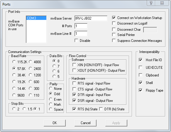
Using DTR/DSR signals flow control with Terminals
To connect a terminal with hardware flow control, the outgoing DTR signal pin from the terminal is connected to the incoming DSR signal pin of the system's I/O controller connector.
The I/O controller connector's outgoing DTR signal pin would be connected to the terminal's incoming CTS signal pin.
From the mvBase Workstation tab, Ports configuration, clear XIN Flow, XOUT flow and DTR state check boxes.
Select the DTR In Flow and DSR Out Flow check boxes.
Click OK.
A warning message displays.
"Changing the protocol will change the actual hardware settings. Are you sure?"
Click Yes to save.
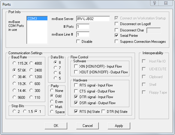
Using DTR/DSR signals flow control with Serial Printers
To connect a serial printer with hardware flow control, the outgoing printer busy signal pin is connected to the incoming DSR signal pin of the I/O controller connector.
To connect a serial printer using DTR/DSR signals:
Clear XIN Flow and XOUT flow check boxes in the Ports dialog box.
Select the DSR Out Flow, DTR In flow, and serial printer check boxes as displayed below.
Occasionally, users encounter a situation where they are unable to connect additional mvBase Clients (mvTerm, telnet sessions, terminals, or modems attached to COM ports and so on) because the mvBase Server believes that all licenses are in use.
This is always due to an inappropriate or inaccurate configuration of the mvBase Clients in the mvBase Workstation, or the lack of disconnection control being specified at TCL.
What often happens is one or more of the following:
mvBase Administrators configure the mvBase Workstation COM port client to Connect on Workstation Startup and forget that they do not have terminals (or other devices) attached to all the COM ports they're connecting to the Server.
Specifying Connect on demand (which is when the Connect on Workstation Startup check box in the Com Port client configuration in the mvBase Administration utility is clear) causes the COM port clients with no terminals or other serial devices attached to them to not consume licenses.
mvBase Administrators configure the mvBase Workstation COM port clients and then use them for serial printers, but forget to set the Serial Printer check box. This causes the serial printer clients to consume a license unnecessarily.
Similarly, the mvBase Telnet Server Clients can be used to accept connections from Network Terminal Servers that have serial printers attached to one or more of their ports. Each port used for a serial printer (as opposed to a terminal or modem) attached to a Network Terminal Server should have the Serial Printer check box selected.
Customers have more terminals than licenses and only expect to have some of the terminals in use at any one time. When terminal users logoff, they forget to manually disconnect from the server, thus continuing to consume a license.
They should either use the Disconnect on Logoff feature available in the COM port client, or the AUTO-DISCONNECT TCL verb, (or less preferably, alter their OFF TCL verb to be a Proc or mvBASIC program which executes a DISCONNECT verb before executing OFF).
mvBase Administrators set up one or more mvTelnet telnet Servers and have users connecting in from other systems. Each connection consumes a license since the Telnet Clients are on a different system to the mvTelnet Server (which is where the mvBase Workstation is being run). Then, after the users have logged off, they forget to disconnect their telnet session, and thus, continue to consume a license.
They should use the AUTO-DISCONNECT TCL verb. To ensure that the client disconnects when the user has logged off.
If a problem still appears to exist with licenses being unexpectedly consumed after eliminating all of the above causes, then, when the licensees appear to run out, do the following:
STOP everyone from logging OFF or disconnecting clients.
The following quick actions require a static environment in order to be meaningful so that the information gathered represents the out of licenses situation.
Log on to the DEMO account and run the USYS command. This displays the number of users connected and the number of licenses that those connections consume.
Run a LISTLINES (A or a LISTLINES command at TCL to see how many LINES have clients connected. (The client type should display mvTerm, Telnet: xxxx, the name of a Windows printer, or a COM port #.)
Reconcile all the information you gather to see which clients are using the licenses.
Whenever an mvBase spool file containing a print job is despooled to a printer, the despooling process examines the print job for linefeed (LF) and formfeed (FF) characters. When it finds them, it inserts into the output stream a number of ASCII NUL characters (x00) that act as delay characters. These characters were intended to allow the print head on slow dot matrix printers, or the paper handling mechanism on serial printers and line printers to complete their movements for line feeds and form feeds.
With the advent of laser printers, inkjet printers, and more modern printing technologies, these delay characters are generally no longer necessary and could be set to 0 (especially since they can cause problems for some printers or specialized output devices such as plotters).
These delay parameters can be set using the TERM or SET-TERM TCL commands as below:
SET-TERM [width, depth, skip, lf-delay, ff-delay, backspace, ptr-width, ptr-length, type] [(n [-m])] |
TERM [width, depth, skip, lf-delay, ff-delay, backspace, ptr-width, ptr-length, type] [(R)] |
lf-delay |
Number of null characters output after each carriage return. These delay characters provide a pause for terminals or printers that cannot display characters as fast as the CPU outputs them. The default value is 1. The maximum value is 127. |
ff-delay |
Number of null characters output after a form feed character for either the terminal or the printer. The default value is 5. The maximum value is 127. If you specify 0, no form feed character is sent to either the terminal or the printer at the beginning of a page. If you specify 1, a form feed (FF) character is sent to the printer (hexadecimal 0C, CHAR(12)), but not to the terminal. If you specify 2 or greater, the form feed character is sent to both the printer and the terminal. |
When setting these delay parameters to 0, it might be expected that the process running the despooler (which is started by the STARTPTR TCL command) needs to have its lf-delay and ff-delay parameters set.
In reality, the values for these parameters are taken from the process that started the despooler, that is, the process on which the STARTPTR command was executed.
Thus, if printers are started during the USER-COLD-START Proc, then a TERM ,,,0,0 statement should be executed prior to the STARTPTR command(s) followed by a TERM ,,,1,5 to reset the values to their defaults.
Rocket produces new releases and patch sets for mvBase that offer numerous enhancements and resolutions to known problems. As a support customer, we encourage you to install these on your systems. However, we have noted that a number of customers get themselves into trouble when they do not adequately prepare for an upgrade.
Below is a list of 10 important steps that you should follow when performing an upgrade. Please read them carefully.
Download mvBase Installation instructions or the Release Notes for the new release from the Rocket Web site. Read it. If you have any questions or concerns, contact your VAR or e-mail them to d3mvsupport@rocketsoftware.com and we will provide you with a detailed answer.
Read the instructions and understand them.
Perform a backup of your mvBase system by doing a full FILESAVE. Verify that it is a good backup. Backing up the Windows files which contain the mvBase Database is not considered a backup for the purpose of preparing for an upgrade. A backup that encounters file inconsistency errors in the file system is not a good backup. You should contact Customer Support to resolve any file inconsistency errors prior to upgrade.
Make sure that you have the ability to reinstall any third-party MultiValue software that you have installed. If you are performing an upgrade that requires recompiling (a very rare situation - but check in the Install Guide or Release Notes) and you do not have all the source code to your application, that application will NOT run after the upgrade.
Verify that all applications that you are running have been tested on the mvBase Release. You may need to contact your application Vendor for this confirmation.
Have a backup copy of all items that may have been modified. This would include SYSPROG, mvBase system accounts, and any item that you or your application might have altered. These items may need to be restored after the upgrade is complete. The upgrade updates the SYSPROG account and some items on all other accounts which are reserved for mvBase use only. This includes all master dictionary entries that come from the NEWAC file in each account and attribute 2 of all logon Procs. Also have a copy of your current activation code, your System ID, and server and workstation configuration information in the chance event that mvBase will need to be installed from scratch.
Schedule the upgrade for a time that would be convenient for business operations, for your VAR, and within Rocket’s Customer Support hours. Any Rocket support given after contracted hours WILL be billed on a time and materials basis, regardless of extenuating circumstances. After hours support for Rocket can be purchased in advance or a support contract can be upgraded.
If something unexpected occurs during the upgrade, STOP. Call Customer Support. Trying to remedy a situation that is unexpected with actions which are not based on a clear understanding of what the problem is and what caused it can have serious ramifications and make the problem worse.
Have the latest patch set for the release that you are upgrading to available for you to install immediately after the upgrade is complete. Only the latest Patch Set should be applied. Note: Patch sets are designated for a particular mvBase release and should not be applied for any other mvBase release. See the mvBase Patch Area on the Rocket Web site. For your own benefit, read and follow exactly the Patch Set installation instructions (also on the Web).
All mvBase components that are not located on the main server system will have to be upgraded as well. This includes any remote workstation components and mvTerm components.
The mvTerm Client application has extended the functionality of its copy and paste feature from earlier releases to include back pages. Because the implementation of back pages causes some adjustments to the handling of screen page dimensions when resizing the mvTerm window, an explanation of page parameters is required to help prevent confusion.
The mvTerm Client in mvBase 2.0 and up
Starting in mvBase Release 2.0, the mvTerm Client application provides the back page capability, which allows the user to view the current screen page, and as many previous back pages that have been viewed. To allow the user to easily view the information in mvTerm's screen pages, the mvTerm Client application provides menu entries and toolbar buttons that scroll to specific offsets within the screen pages. The copy and paste feature for selecting text (by dragging a pressed left mouse button over screen text) has been extended to scroll the mvTerm window up or down when the mouse cursor is positioned above or below the mvTerm window. This window scrolling allows text to be selected in multiple screen pages.
To allow the correct display of screen text when scrolling over screen pages, no unused areas of the window can exist (that is, blank space caused by increasing the vertical size of the window). Also, the number of entries in mvTerm's internal screen array buffer must match the exact total number of rows (page depth) in all screen pages (all back pages + current screen page). To satisfy this requirement, the mvTerm Client application must adjust its screen page depth parameter whenever the depth (vertical) size of the mvTerm window changes. If the user increases the depth of the mvTerm window by dragging the window border, the page depth parameter of mvTerm's screen page gets adjusted to match the new depth (vertical) size of the mvTerm window. For example, if the mvTerm window is currently configured for 20 rows (page depth) and the user drags the window border so that 30 rows exactly fit into the new depth (vertical) size, the mvTerm application automatically sets its screen page depth parameter to 30 rows.
The same mechanism for automatically changing the page depth parameter exists in the mvTerm application when the mvTerm window is maximized. However, when the maximized window is restored, the page depth parameter is adjusted back to its original value.
Even though the mvTerm application adjusts the size of its page depth parameter when the user drags the window border, it does not adjust the size of its page width parameter. The mvTerm application could have been implemented to adjust its page width parameter, in the same manner as it adjusts its page depth parameter. However, if this page width adjustment was incorporated and the user wanted to reduce the width of the mvTerm window to allow more room on the desktop, the data in each screen pagerow would be truncated to the adjusted Windows width value and data would be lost. Because there wasn't the same requirement for the page width parameter to support scrolling that existed for the page depth parameter, it was decided that it would be inappropriate for the mvTerm application to force an adjustment of the page width parameter and cause display of data to be lost.
No display of data is lost by adjusting the Windows page depth parameter when the user reduces the depth of the mvTerm window, because the extra screen rows are automatically stored in the back pages. However, if there are no configured back pages, the ability to display that data is lost.
The current page width and page depth parameter values are displayed in the mvTerm application's status bar to give the user visual feedback on the current dimensions of the mvTerm window.
Starting in mvBase Release 2.0, the controls for the Page Depth and Page Width parameters are edit fields with corresponding spin controls, which allow a full range of values (page depth = 1-75 and page width = 1-132). Both the page depth and page width parameters get adjusted when the user changes the parameter values in the Page Size property sheet and click OK. If the user does not desire the behavior with dragging the mvTerm window border causing the page depth to be adjusted, the user can choose to only adjust the mvTerm window dimensions by making changes in the Page Size property sheet.
When the page depth and page width parameters get adjusted by changing the parameter values in the Page Size property sheet, by dragging the window border, by maximizing the window, or by restoring from a maximized window, these parameters get saved away as the current settings in an mvTerm user profile. When starting a new mvTerm session, these saved user profile settings are used for the initial dimensions of the mvTerm window. When opening a configuration file (.vtm) or when the mvTerm application detects a default configuration file (default.vtm) when starting a new mvTerm session, the parameters in the configuration file will be used instead of the parameter settings in mvTerm's user profile. If adjustments to the page depth and page width parameters cause problems when starting mvTerm sessions, the user can use configuration files to force a specific initial configuration when starting an mvTerm session.
The mvBase operating environment has a mechanism for specifying the page depth and page width parameters for terminal output. These parameters can be specified by the TERM command. In most cases, these parameters of the TERM command should match up with the same parameters in the mvTerm session's configuration. Mismatches in these parameters could cause problems in displaying the screen page data. For example, if the TERM command's page depth is set to 20 and mvTerm's page depth is set to 25, the user will see 5 blank rows at the bottom of the screen page in the mvTerm window. If the TERM command's page depth is set to 25 and mvTerm's page depth is set to 20, the user will only see the last 20 rows of the screen page and the 5 top rows of the screen page will be moved into the bottom of the most recent back page. If there are no configured back pages, the 5 top rows will be lost to viewing. If the user is experiencing these type of display problems, there may be a mismatch in the parameters of the TERM command and the mvTerm application.
The mvBASE Server can use the 3GB option (available on some Windows hosts) to reduce the overhead associated with the support of VMS files (essentially, less disk I/O). To allow the mvBase Server to use the 3GB option, the "/3GB" switch must be added to the System Startup string in the "boot.ini" file.
Additionally, a new boot-time registry value is available to allow the user to change the amount of reserved Virtual Address Space (VAS) for features other than VMS file support. The default reserved VAS is 512 MB.