Adding UTS screens
The Edit Screen Settings dialog is used to add and edit the UTS configuration screens. It contains the Screen Connection and Screen Settings tabs.
Screen Connection tab
The Screen Connection tab defines the screen name and connection route information.
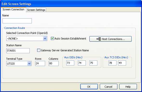
- Name
- Type a name for the screen you want to configure. Up to 24 screens can be configured.
- Connection Route
Selected Connection Point: Select a configured route to be used when the screen is opened.
The first time this screen is accessed, the only available option is <NONE>. You must configure your host connections by clicking Host Connections. Refer to Configure connections for more information.
Auto Session Establishment: Enables auto session establishment.
Station Name: Type the name of the station.
Gateway Server Generated Station Name: Enables the Gateway server generated station name.
Terminal Type: Select the terminal type.
Options include:UTS20
UTS30 (and UTS40)
UTS60
The default is UTS20.
Rows: Type the number of rows allowed in a screen.
The default is 24 rows.
Columns: Type the number of columns allowed in a screen.
The default is 80 columns.
Aux DIDs (Hex)
The default is 73, 74, 75.
Aux TCS DIDs (Hex)
The default is 7B, 49.
Screen Settings tab
The Screen Settings tab controls the screen, trace, and printer options.
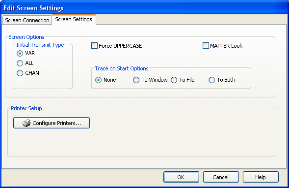
- Screen Options
Initial Transmit Type: BlueZone UTS emulation provides three modes of transferring data from the terminal screen to the host processor. The current transmission mode is set in the XMIT() field in the terminal control page. Most host programs expect the terminal to be operated in the VAR transmit mode. If your application requires an initial mode other than VAR, set it here and BlueZone UTS will initialize the XMIT() field with that value.
The three available modes are:- VAR (Variable)
- ALL
- CHAN (Changed)
- Force UPPERCASE: BlueZone UTS translates lower case characters that are typed to their uppercase equivalents.
- Mapper Look: BlueZone UTS is set to Mapper
Look and Feel processing. With Mapper Look checked, four of the display
characteristics of BlueZone UTS change as follows:
- If a line contains an ASCII Tab Code in the first column, that line is considered a “Tab Line”. Tab codes are displayed using the graphic vertical bar (|) that produces a visual column separator for your report.
- The only control characters displayed are the Start-of-Entry (SOE), the standard Tab Code, and the Mapper Tab Code. Characters such as Form-Feed and Line-Feed are displayed as spaces.
- A protected field (function key name on the last row of the Mapper screen) can be transmitted by clicking. This is compatible with the function key lines produced by Mapper 2200 level 35.
- BlueZone UTS also supports special Mapper box drawing sequences
sent from the host. Note: When Mapper Look is enabled, the Mapper station must be configured as a terminal type of “PCE” with an option of “S” (Mapper Look and Feel), or as a terminal type of “6S”.
- Trace on Start Options: The options in this group determine what trace activity is to take place, if any, when the screen is first opened:
- None: No tracing activity takes place.
- To Window: A separate trace window opens to display the trace.
- To File: The Emulator Trace File dialog opens when the screen is opened. In this dialog, type the text file name for the trace file. The trace file is normally stored in C:\Documents and Settings\username\Local Settings\Temp directory and has a .txt extension.
- To Both: Traces to both a window and file.
- Printer Setup
- Configure Printers: Opens the Select Configured
Printers dialog. In this dialog, you can select a configured printer
in the printer pool to be assigned to one of three printer DIDs for
the screen.
Refer to Configure the screen printer for more information.